Make your own accelerometer controlled motor vehicle
Accelerometer Controlled Vehicle
featuring
MSP430 Launchpad
Introduction:
Imagine controlling the movement of a miniature vehicle by just the wave of your hand! It involves controlling the forward, backward, left and right movement by just the flick of your palm. Besides options such as image processing, using accelerometers is the best possible way to set about accomplishing this task. All you have to do is, to solder the circuit containing the accelerometer onto a small board and attach it to your wrist. Then due to the change in the G-force (gravitational force combined with the small acceleration produced by our hand as you tilt it), a continuous voltage variation is obtained at the accelerometer outputs. You can then program the msp430 to control the motors according to the extent of the change in voltage along the two axes i.e. x and y axes. Let us look into the components required and their applications in this project.
The whole setup could be split into 3 modules:
1).Input:-Accelerometer
2). Controller (Interface):-MSP430G2553
3).Output:- Motor Driver
Let us now deal with each one of them separately.
Accelerometers are not devices which we are unfamiliar to us. Nowadays they are present in almost all touch screen mobile phones. The change in viewing mode from landscape to portrait or the motion gaming in phones is all made possible with accelerometers. Basically these Micro Electro-Mechanical Systems (MEMS) devices that can sense static or dynamic acceleration i.e. it can even sense the acceleration with which you move it in addition to the constant gravitational pull downwards. Because they are affected by the acceleration of gravity, an accelerometer can tell us how it’s oriented with respect to the Earth’s surface. This feature is what is used in our phones to switch between the two viewing modes which were mentioned above. An accelerometer can also be used to sense if a device is in a state of free fall. This feature is implemented in several hard drives: if a drop is sensed, the hard drive is quickly switched off to protect against data loss.
When the sensitivity axis points directly to the center of the Earth, it measures 1g (assuming no additional hand acceleration in this direction). When the accelerometer sensitivity axis lies parallel to the surface of the Earth, it measures zero acceleration. When using an accelerometer to measure the tilt of a hand-held device, the movements of the hand create additional accelerations components. So, when the acceleration measured is anything in between zero and 1 g, we can conclude that it is held at an angle to the earth’s surface. By sensing the amount of dynamic acceleration, you can analyze the way the device is moving. The accelerometer featured here has two output pins to quantify the change in voltage accordingly as it is accelerated along the two axes i.e. x and y axes. Three axis accelerometers are also available which gives additional information about the movement along z axes too. So basically, an accelerometer is an electromechanical device that will measure acceleration forces and give an equivalent analog voltage output.
Analog to Digital Conversion (ADC):
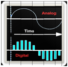
ADC is one of the most important features of a microcontroller and it is used to convert an analog voltage to a digital value. Continuously varying analog inputs are split into discrete quantized bands. There are many modes in which this feature works such as, 2 channel, 4 channel, 8 channel, 10 channel modes etc. Suppose, the maximum value of our analog voltage input is 3.3 volts which is the case with the accelerometer used, then, in a ‘x’ channel mode (x=2,4,8,10), this voltage of 3.3 volts will be split into 2^x discrete bands. The higher the value of x, the more accurate will the digitally converted output will be .i.e. the value of the converted output tends to become closer to the analog input as the value of x increases. For ex: in 2 channel mode there will be only 4 discrete bands each with a range of (3.3/2^2)=.825 volts. So if the instantaneous analog input is say, 1.5 volts, the digitally converted output will still remain just .825 volts since the next discrete band starts only from 1.65 volts. Here the absolute error in the output is very high (1.5-.825 volts). But if the channel mode is increased to say 10 channel mode, then each discrete band will have a range of .00322 volts which implies that the digital output will be nearly the same input analog waveform. (Note: The max. voltage is divided by (2^x – 1) for the range of each band). In this case, the 10 bit ADC in g2553, implementing Successive Approximation Algorithm will be used for the purpose of analog to digital conversion. Here, an input voltage of Vss(0V) to Vcc(3.3V) will be scaled to a digital value ranging from 0 to 1023. Therefore, the digital equivalent of an analog voltage of 1V will be 310.
But why do ADC at all? This is because you can instruct the microcontroller to do specific actions for different input voltages falling into any one of these discrete quantized bands, for, a microcontroller cannot be made to directly differentiate between close values of voltages if a continuously varying analog input is fed to it directly.
The 3 main registers required to configure the ADC in g2553 are:
- ADC10CTL0
- ADC10CTL1
- ADCMEM
Given below is the procedure to turn on the ADC feature at a pin and start the conversions:
- Turn on ADC (Make ADC10ON high)
- Select upper and lower reference values (SREF_x)
- Select Clock source, divide it(prescale) if needed (ADC10SSEL_x + ADC10DIV_x )
- Select Channel (PIN) to be converted (INCH_x)
- Enable ADC option on that pin (ADC10AE0)
- Select ADC Sample and Hold time (ADC10SHT_x)
- Select Conversion Mode (CONSEQ_x)
- Enable Conversion (ENC)
- Start Conversion (ADC10SC)
- Wait for Conversion to end (ADC10BUSY)
- Store ADC value in ADC10MEM register
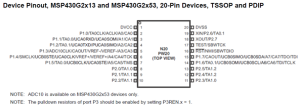
As we had discussed previously, there are 2 output pins in the accelerometer; the XOUT and YOUT. These two pins are in turn connected to two analog input pins of msp430, P1.0 and P1.1.
The ADC feature at these pins is enabled and conversion of the voltage input is started. In addition, for each motor to be controlled, there are provisions for two input pins in the l293d IC. So, four pins from the microcontroller are connected to the two input pins of each of the two motors. Now corresponding to each pair of ranges of the ADC value output that is received from P1.0 and P1.1, the required input pins to the motor are to be made high or low as per the requirement of motion. For ex: if the ADC value pair at P1.0 and P1.1 read a particular value, and we want to make the both motors move forward for this pair of ADC values, then we set the status of the input pins of the two motors accordingly such that both motors rotate in the forward direction. This is explained in detail below under the section Motor Driver.
Motor Driver:-L293D
L293D is a dual H-bridge motor driver integrated circuit (IC). The current from the microcontroller is only of the order of 1µA which is not sufficient to drive the motors. Therefore motor drivers are used which act as current amplifiers since they take a low-current control signal and provide a higher-current signal which is used to drive the motors.
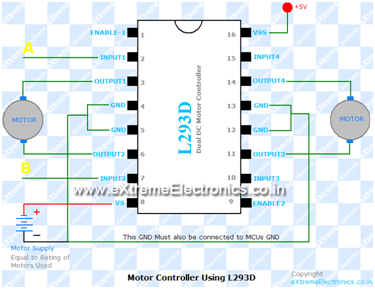
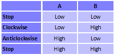
L293D contains two inbuilt H-bridge driver circuits. In its common mode of operation, two DC motors can be driven simultaneously, both in forward and reverse direction. The motor operations of two motors can be controlled by input logic at pins 2 & 7 and 10 & 15. Input logic 00 or 11 will stop the corresponding motor. Logic 01 and 10 will rotate it in clockwise and anticlockwise directions, respectively.
Enable pins 1 and 9 (corresponding to the two motors) must be high for motors to start operating. When an enable input is high, the associated driver gets enabled. As a result, the outputs become active and work in phase with their inputs. Similarly, when the enable input is low, that driver is disabled, and their outputs are off and in the high-impedance state.
Control with MCUs
As the MCUs PORT outputs are not powerful enough to drive DC motors directly, we need some kind of drivers. A very easy and safe is to use popular L293D chips. It is a 16 PIN chip. The pin configuration is as follows.This chip is designed to control 2 DC motors. There are 2 INPUT and 2 OUTPUT pins for each motors. The connections is as follows:
The behavior of motor for various input conditions are as follows
Now refer to Figure a below:
If we want to rotate the motor clockwise, we make the left upper switch and right lower switch closed (which corresponds to A low and B high above) and if it has to rotate in anticlockwise direction, we close the right upper switch and the left lower switch which corresponds to A high and B low. Also for the forward motion of the vehicle we make both motors rotate in clockwise sense (say) and for backward motion, both motors should rotate anticlockwise. For right turn, right motor should stop and left motor should rotate in clockwise direction and for sharp right turn right motor rotates in clockwise direction and left motor in the anticlockwise direction. A similar technique is followed for left turn and sharp left turn which you can easily guess.
So you saw you just need to set appropriate levels at two PINs of the microcontroller to control the motor. Since this chip controls two DC motors there are two more output pins (output3 and output4) and two more input pins(input3 and input4). The INPUT3 and INPUT4 controls second motor in the same way as listed above for input A and B. There are also two ENABLE pins they must be high (+5v) for operation, if they are pulled low (GND) motors will stop.
Speed Control
The speed of a DC motor can also be controlled with MCU. Pulse Width Modulation technique can be used to digitally control the speed (rpm) of DC motors.
General Control Algorithm
Overall circuit layout
Code:
#include “msp430.h”
void main(void)
{
int adc_val1 , adc_val2;
WDTCTL = WDTPW + WDTHOLD; // Stop WDT
P1DIR=0x20; // P1.5 to output
P2DIR|=0x07;
while(1)
{
ADC10CTL0 = SREF_0+ADC10SHT_2 + ADC10ON; // Use Vcc/Vss for Up/Low Refs, 16 x ADC10CLKs, turn on ADC
ADC10CTL1 = INCH_1+SHS_0 + ADC10SSEL_0 + ADC10DIV_0 + CONSEQ_0; // P1.1 input, use ADC10CLK div 1, single channel mode
ADC10AE0 |= 0x02; // PA.1 ADC option select
ADC10CTL0 |= ENC + ADC10SC; // Sampling and conversion start
adc_val1=ADC10MEM;
adc_val1= adc_val1/4;
ADC10CTL0 = SREF_0+ADC10SHT_2 + ADC10ON; // Use Vcc/Vss for Up/Low Refs, 16 x ADC10CLKs, turn on ADC
ADC10CTL1 = INCH_0+SHS_0 + ADC10SSEL_0 + ADC10DIV_0 + CONSEQ_0; // P1.0 input, use ADC10CLK div 1, single channel mode
ADC10AE0 |= 0x01; // PA.0 ADC option select
ADC10CTL0 |= ENC + ADC10SC; // Sampling and conversion start
adc_val2=ADC10MEM;
adc_val2= adc_val2/4;
if((adc_val1 >140)&&( adc_val2>140))
{
P1OUT|=BIT5;
P2OUT&=~0x07;
}
else if((adc_val1 >140)&&( adc_val2<120))
{
P1OUT&=~0x20;
P2OUT&=~0x05;
P2OUT|=0x02;
}
else if ((adc_val1 >140)&&( adc_val2>120)&& (adc_val2<140))
{
P1OUT|=BIT5;
P2OUT&=~0x05;
P2OUT|=BIT1;
}
else if (adc_val1 <120)
{
P1OUT&=~0x20;
P2OUT|=0x05;
P2OUT&=~0x02;
}
else
{
P1OUT&=~0x20;
P2OUT&=~0x05;
P2OUT&=~0x02;
}
}
}
*NOTE: In order to use Pins 1.0 and P1.1 as ADC input, the UART jumper which is by default fixed on the board, must be removed.


hi…
can anyone tell me that wat is the software used for compiling this program…. and where is this ADC chip burner available….
LikeLike
the softwar used for compiling code for msp430 is Code Composer Studio. If you are using an AVR microcontroller, you can use AVR studio. ADC is an inbult feature i the microcontroller which can be Incorporated through coding.
LikeLike